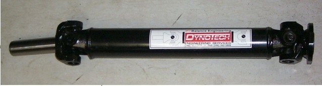
I bought some more of Jim Biondo's used stuff. He had a steel driveshaft that he wasn't using that was a few inches longer than what I needed (19.75"). Jim took the shaft and my front (for the Tremec 5spd) and rear (for the R200) yokes to Dynotech (ITW) in Michigan for them to shorten the shaft, install new Spicer U-joints, and high speed balance the unit. Dynotech is one of a few places in the USA that have high speed balance equipment. With the history of driveline vibrations that I've witnessed in V8 Z's, I thought this was good insurance - although I think the problems I've seen are driveshaft u-joint angle related.
(1) The driveshaft u-joint yokes are not exactly
phased. That is, the centerline through the u-joint cups at the two
ends of the shaft are not parallel, but "twisted" about the shaft centerline.
(2) The u-joint cap centerlines are not both
perpendicular to the shaft centerline.
(Note: Any decent driveshaft shop knows how to get (1) and (2)
right, and know their importance.)
(3) The differential pinion centerline and
crankshaft/transmission shaft centerlines must be parallel (in the vertical
and horizontal planes.)
(4) The u-joint angles must be below a certain maximum
value for a given "average" rpm under load. (See this
page for details.)
Using the JTR trans mount bracket/crossmember and an old style Ford trans mount (1.79" high) and having the R200 differential bolted into the stock location, I measured the pitch of the differential pinion (using the pinion flange) and the crankshaft/transmission shaft (using the starter mounting surface or the front surface of the harmonic balancer). The pitch angles were different by 1.5 degrees. The difference was the result of the differential pinion centerline being more nose-up (relative to the ground) than the crankshaft centerline. Having ridden in two V8 240Z's that have drivetrain vibration/noise issues under hard acceleration, I decided to make the u-joint angles as similar as possible. This would ensure that the u-joints would not cause a significant speed variation at the differential relative to the transmission. The centerlines in the horizontal plane were parallel.
I made three modifications to the mounting of the engine/transmission and the differential to try to get the u-joint angles more similar (i.e., get the crankshaft and pinion centerlines more parallel in the vertical plane) and to optimize them to around 1 degree each:
(1) The first thing I did was remove the 1/2"
spacer blocks that JTR says to use between the frame rails and crossmember.
This makes the crankshaft/tranny centerline pitch closer (more nose up)
to the pitch of the differential pinion centerline and has the added benefit
of giving more ground clearance under the oil pan and bellhousing (for
a given ride height). Those 1/2" spacers lower the engine crossmember,
so removing them would raise the front of the engine/transmission combination.
With a relatively high rise intake manifold (Holley Contender), a 750cfm
Holley carb., and a 14" Moroso drop base air cleaner with a 3" filter ,
I still have 1/2" of clearance between the stock, unmodified hood and air
cleaner.
(2) The second thing I did was to raise the
rear of the differential to make the pinion angle less nose up relative
to the ground. I raised it ~0.45". The details are in the Differential
section toward the end of this page.
(3) (update March 2002) The third change
from stock was to use a totally different front differential mount, which
lowered the front of the diff considerably.
The result of the first modification yielded driveshaft angles of about 7 degrees, within about 1/2 degree of each other. After writing a spreadsheet to analyze the speed error at the back end of the driveshaft (relative to a constant front rotation rate), I decided that the speed variation with 7.5 and 7 degree U-joint angles was acceptable (+/-0.111% max error). But I still had a problem, read on.
I've read lately that for 5000 rpm average driveshaft speed, you need the driveshaft u-joint angles to be 3.25 degrees or less, or you will get vibration. (See this page for details.) The reason for the large U-joint angles in the V8 Z with the JTR transmission crossmember and the Tremec 5spd and 1.79" high Ford trans mount are that the driveshaft is short (roughly 20 inches) and that the transmission slip yoke centerline is several inches below the differential yoke centerline. The referenced web page also gives the following as a guideline for determining the maximum permissible u-joint angle:
"When the transmission output shaft centerline and axle input shaft centerline are parallel, the u-joint operating angle permissible is length of driveshaft divided by five. Example: A short coupled driveshaft with a 15" length would be limited to 3 degrees maximum operating angle. A 30" shaft would be limited to 6 degrees."So, for my ~20" driveshaft, the angle should be about 4 degrees or less.
For the second driveline mounting modification, I raised the transmission mount. In order to decrease the u-joint angles, either the rear of the transmission must be raised and/or the front of the differential must be lowered. Since raising the rear of the transmission is much easier than lowering the front of the differential, I first concentrated my efforts on raising the back of the transmission.
The Tremec is very wide at the top of the case. This limited the amount I could raise the rear of the transmission to about 5/8" to provide adequate clearance (3/8") between the Tremec case top and my already-close-to-the-tunnel brake line. This was done by adding a 5/8" thick aluminum block spacer between the Tremec transmission mounting pad and the 1.79" high Ford transmission mount. This configuration used the JTR transmission crossmember.
After raising the rear of the transmission by 5/8", the
driveshaft angles are 3 degrees (rear) and 3 degrees (front). Since
the u-joint angles are equal, the maximum speed variation at the rear of
the driveshaft is in 0.0004% (-.0002% to +.0002%) error, as opposed to
0.22% (-.11% to + .11%) error with the original 7 and 7.5 degrees.
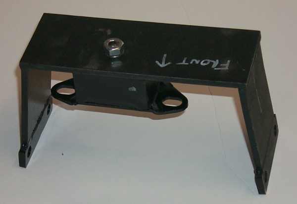
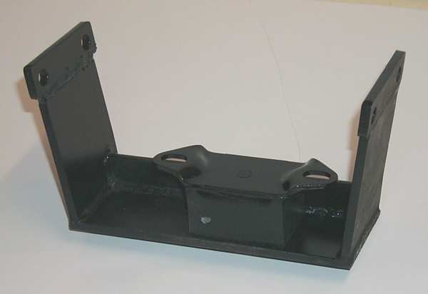
The rubber mount seen is simply a GM transmission mount, the same one specified by JTR for use at the transmission. In order to get the u-joint angles the same after this modification with the GM rubber transmission mount, I added some thick washers under the Ford transmission mount above the transmission crossmember, The result of lowering the front of the differential with this setup, along with the other 2 mounting modifications, resulted in driveshaft u-joint angles (in the vertical plane) of 1 degree front and 1 degree rear. This is optimal. The result is an incredibly small 0.0000023% output rotational speed error at the differential (assuming a constant input rotational speed) -virtually no error. The engine produces a non uniform rotational speed several if not many times larger. But 1 degree of U-joint angle is enough of an angle to allow the u-joints to move enough to keep the grease moving around to prevent brinneling of the u-joint trunnions.
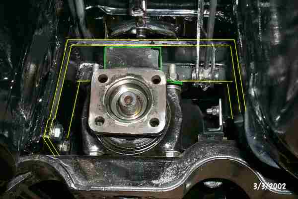
The GM transmission mount is simply a brick of soft rubber with steel plates adhered to it top and bottom. This part soon ripped apart, even on the first test drive. I replaced it with a polyurethane GM transmission mount from Energy Suspension Products, Part number 3-1108. This part comes with a steel plate that is supposed to be inserted between the transmission (differential in this case) and the mount. There was not enough room to install this plate, as it would have made the differential nose interfere with the crossmember below it, so I left it out.
The only drawback is there's little room above this
bracket for the parking brake mechanism. I used an extra spring that
holds the u-shaped part of the parking brake cable to the body. I
bolted one end of this spring underneath the head of one of the bolts that
holds the parking brake levers above the front of the differential and
looped the other end of the spring around the rod that connects the U shaped
bracket for the cable to the levers there. This holds the linkage
above the new differential mount bracket so that it won't rattle against
the bracket.
These three driveline component mounting modifications (raising the rear mounting of the differential, raising the rear of the transmission, and lowering the front of the differential) leave the units at non-OE pitch angles relative to the standard pitch.
As for the differential, I will fill the case until the level is flush with the bottom of the fill hole. This will raise the oil level to just a small fraction of an inch above the stock condition at the pinion, but keep the pinion gear, carrier and ring gear submerged in oil to a near stock level in the case. There is a possibility of pinion seal seepage, and I will keep an eye on this. If seepage is a problem, I will consider lowering the oil level by 1/4" at the rear to compensate.
As for the engine and transmission, I will fill these to their rated capacities. The issue of carburetor pad pitch (generally 3 degrees nose down relative to the crank centerline) will not be an issue, since the floats on my carburetor are center hung (Holley 3310) and will still swing freely. I might go to the trouble of compensating for the non-standard carburetor pad pitch by adjusting the fuel bowl levels to compensate, but this would be a negligible effect, since the pitch has only changed to about 1.5 degrees nose down. I am assuming that the change in pitch angle is also small enough that oil drainback, etc. in the engine will be not significantly effected.
The departures from JTR are:
In order to:
1) Partially rectify
the severe nose-up attitude of the differential, relative to the angle
the crankshaft/transmission shafts make with horizontal plane (and the
attendant large and different driveshaft u-joint angles) (before
I installed the new fabricated front differential mount setup, this was
an issue.); and
2) Raise the output
shafts of the differential to bring them more in-line with the stub axles
with the car lowered 1.5-2" (alleviating large u-joint angles in the halfshafts
when I still had u-joint halfshafts);
I decided to raise the rear of the differential
by roughly 1/2".
At first, I did this by removing a large (0.125" thick) washer that I had between the upper mustache bar and the body, and by raising the mounting holes for the differential in the mustache bar. To do the latter, I drilled (very difficult in the hardened steel of the mustache bar) and filed new holes 0.4" above where the original holes where. Actually, the lower 1/3 of the new hole was into the top of the original hole. I filled the remainder of the old holes with steel and weld material. I also added about 1/2" of steel along the top edge of the mustache bar, since the new holes were less than 1/2" from the original edge.
But after discussing what I did with several knowledgeable spring technicians and materials engineers, I was convinced that I had weakened the mustache bar by welding on it.
So, I got another stock R200 mustache bar, and this time, I cut 0.3" out of the top of the top polyurethane bushing, and kept the supplied top large steel washer out of the setup. To make this work, I cut 0.3" out of the inner sleeve as well. In all, this raised the rear of the differential by about 0.45" over using the polyurethane bushing kit as supplied.
The effect of raising the rear of the differential
by ~0.45" is to change the angle between the pinion and the horizontal
plane by roughly 1.4 degrees. By the way, you can only raise the
back of the R200 another 1/4" before it gets too close to the transverse
hat stiffener under the floor just above the rear of the diff. I
do not know what the effect of lowering the front of the differential had
on the angle of the pinion.
However, the parts became available, so I proceeded with the CV Halfshaft (280ZX Turbo) Conversion for late 260Z/280Z Stub Axles.